
目录
概述
1 硬件结构
1.1 整体硬件介绍
1.2 硬件连接结构
2 软件设计
2.1 软件功能介绍
2.2 关于Arduino的一些知识点
2.2.1 定时器
2.2.2 PWM
2.3 代码实现
2.3.1 编译工具
2.3.2 详细代码
3 测试
3.1 温度数据监控
3.2 温控测试
概述
本文介绍如何使用Arduino UNO作为主控制板,设计一个智能温控系统,其实现功能如下:当环境温度达到一定的门限值时,开始风扇,当环境温度低于该门限值则关闭风扇。系统使用DS18B20采集环境温度,L298N驱动电机,OLED显示当前环境温度。软件设计上使用Arduino自带的定时器中断功能,用于控制时间间隔。还使用了PWM技术,以控制电机的转速。
1 硬件结构
1.1 整体硬件介绍
1)Arduino UNO: 主控板卡
2)控制L298N:用于控制电机系统
3)控制OLED模块:用于显示当前温度数据
4)控制DS18B20:获取环境温度数据
5)直流电机:驱动扇叶
1.2 硬件连接结构

模块引脚与Arduino UNO主板之间关系:
| Arduino UNO IO | 应用模块IO | 注释 |
| PIN-2 | DS18B20 DQ | |
| PIN-5 | L298N in-1 | 用于电机控制 |
| PIN-6 | L298N in-2 | 用于电机控制 |
| SCL | OLED-scl | |
| SDA | OLED-sda |
2 软件设计
2.1 软件功能介绍
软件主要实现功能如下:
1) 控制DS18B20,读取该传感器采集到的温度值
2) 在OLED显示温度数据
3)通过串口打印调试信息
4)根据门限值,控制电机转速(PWM)
2.2 关于Arduino的一些知识点
2.2.1 定时器
在Arduino中使用定时器,必须要包含该头文件 <MsTimer2.h>,然后调用如下函数启动定时器,并且还要实现一个中断回调函数。
void startTime()
{// 中断设置函数,每 500ms 进入一次中断MsTimer2::set(500, timer_irq);//开始计时MsTimer2::start();
}//回调函数
void timer_irq()
{}
2.2.2 PWM
在Arduino UNO板卡中使用PWM功能,其能使用的引脚为pin( 3, 5, 6, 9, 10, 11),使用方法如下:
1) 配置端口为模拟引脚
2)使用analogWrite( pin, cycle )函数来配置占空比参数含义如下:
pin - 引脚号;
cycle - 占空比(范围: 0 ~ 255 )
一个使用案例:
//for motor port
const int output1 = 5;
const int output2 = 6; // 初始化IOvoid setup()
{pinMode(output1, OUTPUT); pinMode(output2, OUTPUT);
}// 配置占空比void pwmCycle()
{analogWrite(output1, 150);  analogWrite(output2, 0);
}
2.3 代码实现
2.3.1 编译工具
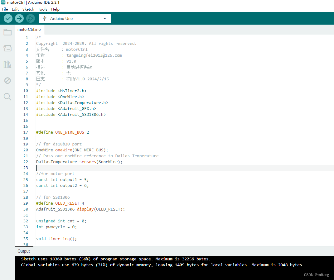
2.3.2 详细代码
/*
Copyright  2024-2029. All rights reserved.
文件名     : motorCtrl
作者       : tangmingfei2013@126.com
版本       : V1.0
描述       : 自动温控系统
其他       : 无
日志       : 初版V1.0 2024/2/15
*/
#include <MsTimer2.h>
#include <OneWire.h>
#include <DallasTemperature.h>
#include <Adafruit_GFX.h>
#include <Adafruit_SSD1306.h>#define ONE_WIRE_BUS 2// for ds18b20 port
OneWire oneWire(ONE_WIRE_BUS);
// Pass our oneWire reference to Dallas Temperature.
DallasTemperature sensors(&oneWire);//for motor port
const int output1 = 5;
const int output2 = 6; // for SSD1306
#define OLED_RESET 4
Adafruit_SSD1306 display(OLED_RESET);unsigned int cnt = 0;
int pwmcycle = 0;void timer_irq();void setup() {Serial.begin(9600);// put your setup code here, to run once:pinMode(output1, OUTPUT); pinMode(output2, OUTPUT); analogWrite(output1, 0);  analogWrite(output2, 0);  // by default, we'll generate the high voltage from the 3.3v line internally! (neat!)display.begin(SSD1306_SWITCHCAPVCC, 0x3C);  // initialize with the I2C addr 0x3C (for the 128x32)display.display();// Show the display buffer on the hardware.// NOTE: You _must_ call display after making any drawing commands// to make them visible on the display hardware!                                                                                                                                            display.clearDisplay();// 中断设置函数,每 500ms 进入一次中断MsTimer2::set(500, timer_irq);//开始计时MsTimer2::start();
}void loop() {int tempPwmCycle = 0;// put your main code here, to run repeatedly:if( cnt%2 == 0 ){sensors.requestTemperatures(); // 发送命令获取温度if( cnt%3 == 0 ){display.clearDisplay();Serial.print("Temperature for the device 1 (index 0) is: ");Serial.println(sensors.getTempCByIndex(0)); display.setTextSize(1);      display.setCursor(0,0);                  // Start at top-left cornerdisplay.println(F("Current temp: "));display.setTextSize(2);                 // Normal 1:1 pixel scaledisplay.setTextColor(SSD1306_WHITE);    // Draw white textdisplay.setCursor(25,15);                // Start at top-left cornerdisplay.println(sensors.getTempCByIndex(0));display.display();}}if( sensors.getTempCByIndex(0) >= 20  ){tempPwmCycle = 100;}else{tempPwmCycle = 0;}if( pwmcycle !=  tempPwmCycle ){pwmcycle = tempPwmCycle;analogWrite(output1, pwmcycle);  analogWrite(output2, 0);  }
}void timer_irq()
{                       cnt++;
}
3 测试
3.1 温度数据监控
采集和打印温度数据信息:

3.2 温控测试
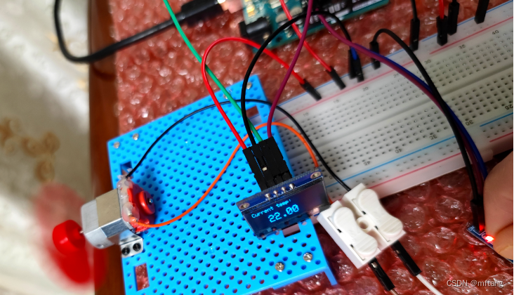
温度值 Value > 20 ℃ ,开启风扇

:120. 三角形最小路径和)


![[C++]内存管理:串顺序存储的内存回收](http://pic.xiahunao.cn/yaotu/[C++]内存管理:串顺序存储的内存回收)

:ArkUI 首页仪表盘搭建)